A "tip-up" is when the machine is cutting a part and the part rotates out of plane, sticking up from the rest of the sheet metal. The machine gets a tip touch when it tries to automatically continue, because the part is blocking the cut path. The machine pauses and you will have to manually remove the part and then press the flashing green continue button to continue the job.
Here are a few ways to prevent tip-ups:
Clamping Down Stock
Sheets that are not flat and/or are too thin to weigh themselves down should be clamped down at the edges of the pallet by the pre-installed screw-down spring clamps. The other edges of the stock that sit in the middle of the pallet should also be weighed down by additional heavy stock. Make sure the additional stock weights do not intersect the job area before running the application.
FabCreator Design Features
1. Add tabs
The best way to prevent tip-ups is to add tabs to your part. FabCreator automatically adds tabs to the end cuts on tube applications, but sheet applications require manual insertion of tabs.
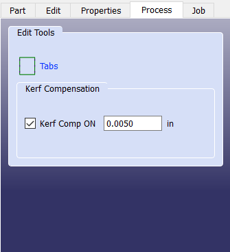
- Open your .fab file in FabCreator and go to the Process tab.
- Click on "Tabs" to enter tab editing.
- The Factory default tab length is 0.01" but you can change this value and all tabs will automatically update to the new value.
- To insert, move, or delete tabs, first click the appropriate button, then click on the tab you'd like to edit in that fashion.
- Hit "Done" to accept your tab edits or "Cancel" to discard changes.

- Be aware that a pair of tabs, particularly if they are placed directly across from one another along a machine axis, may not be enough to prevent tip-up as the part can spin about the axis created by the tabs once cut, as illustrated below:

- Thin or soft stock may also warp during the cut if long parts are placed close by one another, as illustrated below:

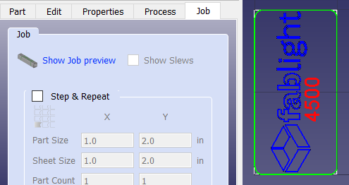
2. Preview the Job Slews
- On the Job tab, you can click "Show Job Preview" to see which entities will be cut (green), engraved (red), or rastered (blue), as will as any reference lines for construction only (black).
- With job preview shown, you can then check "Show Slews" to see the intended travel path of the laser (purple). This can help identify potential roadblocks in cutting head travel path based on feature shapes/sizes and the order they will be cut.

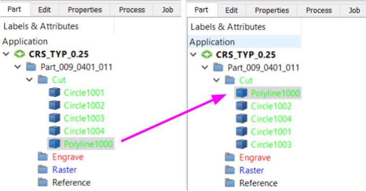
3. Change the Cut Order
You can reorder entities to change the slew path of a file such that, for example, small simple features are cut first and large or complicated features are cut towards the end of the job.
- Go to the Part tab, where all the design entities are organized into a cascading tree.
- Drag and drop entities in the same category in the order you desire. Entities at the top will be operated on by the laser first.
- You cannot change the order of the categories. The laser is hard-coded to perform Raster first, then Engrave, and Cut last.